2019 Top Water & Wastewater Projects
Bob Crossen is senior managing editor for WWD. Crossen can be reached at [email protected]. Cristina Tuser is associate editor for WWD. Tuser can be reached at [email protected].
undefinedIn 2019, WWD had four top projects that topped the editors scoring lists, so to determine which one would be named the #1 WWD Top Project, they held a meeting. While all four presented interesting challenges and creative solutions to problems, the Westfield PFAS Emergency Response project was the unanimous choice.
The project owners, managers and engineers took their efforts one step further by becoming thought leaders on the subject of PFAS and best practices they found while implementing their project. This additional dedication elevated the project, ultimately leading to it being named the #1 WWD
Top Project.
But there are many other strong projects this year on the following pages. From large pipe rehabilitation to smart water programs and facility upgrades, editors were impressed by the quality of submissions this year. While the following pages outline the key points for each of these projects, longer-form write-ups will be available on WWD’s website and the editors encourage you to check them out. Visit www.wwdmag.com/top-projects to read each piece in more depth and see even more photos.
And if you have a project you think is worthy of recognition, links to the nomination forms also are available at the link above. So submit a nomination now to get ahead of the game!
WWD #1 Top Project
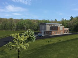
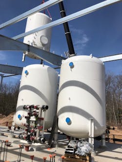
Westfield PFAS Emergency Response
|
Location Westfield, Mass. Size 5,300 gpm Cost $16 million Facility & Project Owner City of Westfield, Mass. Designer Tighe & Bond Inc., CDM-Smith Contractor R.H. White Construction Manufacturers TIGG, Calgon Carbon, Metex/Neptune Chemical Pump Company Inc., Poly Processing Equipment GAC vessels, metering pumps, chemical storage tanks |
In response to PFAS contamination of the Barnes Aquifer, the city has been rapidly bench-scale testing, planning, designing and constructing PFAS treatment systems at multiple well sites to ensure safe drinking water was supplied to residents. The city had goals to construct new treatment facilities as quickly as possible to ensure safe drinking water and to lead broader industry discussion on how to respond to PFAS. Per- and polyfluoroalkyl substances (PFAS) are a group of emerging contaminants that are causing highly charged discussions between regulators, public health agencies, municipal water suppliers and the public. Over the past several years, the city of Westfield has been at the forefront of these discussions.
The city of Westfield has a population of approximately 42,000 people and provides water service through a combination of surface water and groundwater sources. In particular, the north half of the city is served by four wells.
In 2016, the U.S. EPA lowered the health advisory level for Perfluorooctanoic Acid (PFOA) and Perfluorooctane Sulfonic Acid (PFOS) to 70 ppt. Testing confirmed that Westfield’s Well 7 and Well 8 were above the health advisory level and Well 1 and Well 2 were close to the health advisory level.
The city responded by shutting down Wells 7 and 8 prior to the implementation of the health advisory level. The north half of the city has limited hydraulic interconnection with the southern half of the city, so loss of these wells created vulnerability. Water restrictions were implemented, so the north half of Westfield was supplied from the south half, along with limited running of Well 1 and Well 2 as needed.
Later in 2016, Westfield retained CDM-Smith to perform alternative analysis and bench-scale testing of two types of granular activated carbon (GAC) for PFAS removal, finding both coal-based and coconut-based GAC products to be appropriate and cost-effective treatment alternatives for Westfield’s water. CDM-Smith then commenced design of the Owen District Road Water Treatment Plant (WTP) to provide treatment of water from Well 7 and Well 8.
2018 marked Westfield’s plan to retain Tighe & Bond to permit and design a temporary GAC treatment system for Well 2 to allow the city to reactivate this well while the Owen District Road WTP was being designed and constructed.
The temporary treatment system consisted of a concrete foundation, water main and chemical feed piping from the adjacent Well 3 building, as well as a single GAC filter vessel. To date, Well 2 has treated more than 75 million gal of water, which has consistently been non-detect for the targeted PFAS compounds.
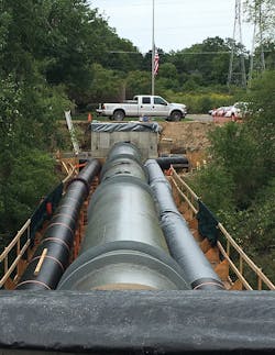
The 2,600 gpm Dry Bridge Road WTP currently is under design by Tighe & Bond. Following evaluation of alternative locations, a site was selected on city-owned property between Well 1 and Well 2. 6,000 ft of raw water piping and 2,400 ft of finished water piping are required as part of the WTP construction because the two wells are not immediately adjacent to each other.
Westfield currently lacks space for staff on the north half of the city, which is a concern given the construction of the two new water treatment plants. The estimated cost of the Dry Bridge Road WTP, including the raw and treated water mains, is approximately $10 million and construction of this facility is anticipated to commence in late 2019.
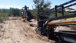
Sabino Creek Pump Station & Force Main
The Pima County Regional Wastewater Reclamation Department (RWRD) operates and maintains 3,500 miles of sanitary sewer lines in Pima County, Ariz. The primary goal of the Sabino Creek Pump Station and Force Main Project was to replace a wastewater gravity pipe wash crossing, servicing an area near Canyon Ranch Resort that crossed the Sabino Creek to the east.
|
Location Tucson, Ariz. Size 284 gpm Cost $2,806,985 Facility & Project Owner Pima County Regional Wastewater Reclamation Department Designer Engineering and Environmental Consultants Inc. Contractor B&F Contracting Inc. Manufacturers Super Products LLC, Vermeer, Sterling, Caterpillar, JCB, Vactor Equipment Directional drill, dump trucks 20, 312C excavator, 347F L, skid steer loader, backhoes |
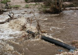
Flooding in 2006 washed out portions of Sabino Creek, exposing the pipeline and making it vulnerable to damage. Temporary stabilization efforts were conducted. However, to mitigate risk and ensure public safety, RWRD constructed a new 36-ft-deep lift station and a 6-in. 3,300-ft force main to eliminate the existing Sabino Creek gravity sewer crossing.
Another aspect of the project was to involve the community while achieving the goals of the project. The Sabino Creek Pump Station services 260 single-family homes and the Canyon Ranch Resort west of Sabino Creek. Both entities requested limited site disturbance, leaving the natural vegetation intact, and that any new structures blend in with the existing landscape.
As the project progressed, it became apparent that the project site was located in an Arizona Upland biotic community, which housed native plant and animal species. A biological evaluation was required to identify the species which might be adversely affected by the project. Another challenge involved the placement of the lift station. There was not a suitable location for utility placement or access to the area for maintenance purposes once the lift station was built, so an original walking path was used for construction access to the site.
It was determined that more than 2,000 ft of the 3,300 ft force main would be directionally drilled. This allowed for the force of the main to go under washes and limit the disturbance of natural habitat. Armorock Polymer Concrete manholes were selected as structural, sustainable and corrosion-proof alternatives to concrete manholes.
The new pump station and force main now provide the primary means of wastewater conveyance in the area, eliminating the exposed pipe and the potential risk of catastrophic failure during a future storm event.
Clinton River WRRF Influent Pipe Rehabilitation
|
Location Auburn, Mich. Cost $1,370,389 Size Not supplied Project Owner Oakland County Water Resources Commissioner’s Office Designer NTH Consultants Ltd. Contractor Weiss Construction Co. LLC Manufacturer Link-Belt, Grove Equipment 200 ton crawler crane, model 248 H5, 75 ton rough terrain crane, model RTC 8075 |
Constructed in the early 1960s for the city of Pontiac, Mich., the Auburn Sewage Treatment Plant is located on the east side of the Pontiac River and serves a significant portion of the community with wastewater treatment services. A 66-in. diameter steel sewer line is the primary influent line for the Clinton River Water Resource Recovery Facility (WRRF), crossing above the Clinton River.
The river crossing pipeline consists of a pile-supported fabricated steel pipeline with a total span of 140 ft, which uses three pipe-pile bents to span the river between underground sections of the interceptor. The effects of time, weather and the internal wastewater atmosphere gradually have deteriorated the steel pipeline.
During a video inspection of the sewer, Oakland County Water Resources Commissioner’s Office staff observed cracks in the sewer at two locations in the middle span over the river. The river crossing pipeline was originally constructed as a discrete segment in the overall influent sewer system but did not include any redundancy or adjacent facilities for a flow bypass procedure necessary to temporarily isolate the river crossing and allow worker access and repairs to take place.
For this project, the overall concept envisioned a bypass piping system with two parallel gravity lines supported by the existing pile bents, capacity-designed to handle both normal dry weather and maximum foreseeable wet weather flows. In addition, the chambers were configured with stop plate guides to allow flows to be maintained through the existing pipeline and when needed, flow could be diverted through one or both of the parallel bypass lines.
The chamber roof deck covers versatile, heavy-duty structural steel fabrications adequate for temporary hydraulic loading as well as potential future vehicular traffic loads. Upon completion of the entire bypass arrangement, those steel plates became the easily installed chamber cover plates readily available for instant reuse in the event of future needs.
The bypass pipelines were quickly demobilized and removed from the project and the diversion chambers were converted to their permanent configuration with the combination stop plate/cover plates secured in place.
The removal and replacement pipeline operation took six days to complete, which was within the maximum 10 day window. A temporary supported walkway platform spanning the three pile bents allowed full unrestricted safe access for the dismantling and erection crew.
“As always, the safety of the workforce completing this challenging task was a critical objective followed closely behind by the need to avoid any disturbance to wastewater flows that would affect the surrounding community served by the pipeline and wastewater treatment plant,” said NTH Principal Engineer Larry Gilbert.
Mt Soma Reservoir
|
Location Bel Air, Md. Size 90 million gal Cost $6,254,677 Facility & Project Owner Maryland American Water Designer Gannett Fleming, Inc. Contractor Allan Myers Manufacturer Coletanche, ADS Inc., Medora Corp, LG Sonic, BIGR Bridge Equipment Reservoir liner, corrugated pipe, solarbee, ultrasonic algae control, prefabricated bridge, check valve, floating wetlands, gate valves, ball valves, combination air valve, reinforced concrete pipe, ductile iron pipe |
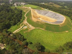
Maryland American Water (MAW) supplies Bel Air-area customers with water sourced from Winters Run. During times of drought, the utility supplemented this supply with water provided by Harford County, but the supply was not guaranteed. In 2014, a temporary purchase arrangement between MAW and the county was approved with the understanding that a long-term back source, independent of the county’s supply, would be secured within four years. The Mt. Soma Reservoir satisfies this requirement, using a 62 ft high earthen embankment with a 20 ft wide crest to store up to 90 million gal of raw water. The water can be conveyed to an adjacent treatment plant as needed for use during drought and emergencies.
The project included a 0.25-mile-long road allowing residents to access the Soma historic site adjacent to the impoundment. The team built the facility without disturbing the 300 year old Mt. Soma barn near the site.
The facility uses sustainable water quality improvement systems to maintain water quality and impede algae growth in the impoundment. At Mt. Soma, seven man-made, floating wetland units hold 4,000 native aquatic plants and cover 3,000 sq ft. of the reservoir’s surface. Microbes in the biofilm surrounding the plants’ root systems break down and absorb algae-promoting nutrients, reducing nitrogen and phosphorus content by approximately 30%. A solar-powered, ultrasonic algae control system removes up to 90% of existing algae in the water and inhibits new growth. A solar-powered water mixer promotes oxygenation and prevents stagnation, maintaining water quality. Both systems use renewable power, reducing environmental impacts.
The impoundment was positioned so gravity could be used to send water to the treatment plant over a 500 ft run, which avoids the use of pumps and saves energy.
Soil at the project site was rich in mica, so engineers completed 50 more laboratory water content tests than were specified in the contract and developed a family of compaction curves applicable to on-site soil, which avoided hauling out or disposing of tens of thousands of cubic yards of material.
“Our work took place during one of the wettest years on record. An earthen dam has very rigorous soil and compaction requirements,” said Likovich. “When you have rain on the exposed soil, prior to completely placing the liner, the soil must be reworked to make sure it meets the specifications of the design.”
A bituminous geomembrane liner (BGM) was used to create a watertight barrier to prevent seepage inside the 2,025 ft long dam embankment and impoundment bottom. BGM liners are more common in Europe than in the U.S., where they are often used in the mining industry. The impoundment marks the second time in history a BGM liner has been used to line a water supply reservoir in the U.S. and the first time on the East Coast.
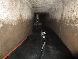
Albany Trunk Sewer Rehabilitation
|
Location Albany, N.Y. Size 100,000 gpm Cost $1,043,000 Facility & Project Owner Albany Department of Water & Water Supply Designer Albany Water Department Contractor Arold Construction Manufacturer AP/M Permaform, Vactor, Envirosight, Allentown Equipment CentriPipe spincaster, Vactor 2100, Rover X Unit, Magnum Putzmeister concrete pump |
Albany Department of Water & Water Supply maintains a combined sewer system containing major components more than 100 years old. Leading up to this project, Albany faced emergency projects with two major sinkholes in Beaver Creek Combined Sewer District, a network providing sanitary sewer and storm drainage for more than 5 sq miles of Albany. The Beaver Creek District’s sewer network infrastructure dates back to trunk sewers built as early as the 1850s.
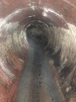
The Albany Water Board contracted a third-party inspection and assessment of approximately 2,600 ln ft of sewer within the Beaver Creek Sewer District. Built around 1895, the majority of the combined sewers inspected were 84 in. diameter brick or monolithic concrete. A segment of 48-in. by 60-in. oblong brick sewer on Warren Street also was inspected. All inspections were performed by manned entry pipe walks.
The key features of this project are the stabilization and rehabilitation of aging and failing structures with careful attention to dewatering and flash flood safety measures while also minimizing disruption to residents and businesses. The department implemented a structural, cost-effective, trenchless sewer rehabilitation solution with a small staging area and short cure time for this purpose.
In affected neighborhoods, the combined sewers typically run directly under street center lines, and right-of-ways are relatively narrow. These are older neighborhoods with minimal setbacks and houses tend to be built near property lines, which means limited staging areas or road closures.
Many sections of large diameter brick sewers were found to be failing, with visible mortar loss and cracks. There also were longitudinal fractures at pipe crowns running continuously along entire sewer sections, with bricks starting to fall out, indicating severe risk of failure and collapse.
Crews took special measures to stabilize them before rehabilitating with a centrifugally cast concrete pipe (CCCP) system. The crown fractures were filled with a specialized fine aggregate composite concrete (FACC) using a hand sprayer. Flexible basalt grid, which does not corrode or pull apart, was pinned over that for reinforcement.
Reliable dewatering was critical for this project. The bypass system needed to handle daily flow, as well as sudden floods from storm events. The depth of the sewers, 25 to 30 ft below ground, added complexity to every aspect. Bypass pumping with submersible pumps ensured dry sewers during two to three hour FACC curing windows. A collapsible weir was deployed upstream in less than a minute during a storm event to protect new concrete layers and allow crews to evacuate. Several storms thoroughly tested the reliability and functionality of this system.
Despite an unusually stormy season, work was completed on schedule, including an emergency change order. The repair should add 50 to 75 years to the lifespan of the sewers.
Texas Medical Center Sewer Rehabilitation
|
Location Houston, Texas Size 34 mgd Cost $4.5 million Facility Owner City of Houston, Texas Medical Center, Houston Parks and Recreation Department Project Owner City of Houston Designer City of Houston, Houston Water/Wastewater Operations Branch Contractor Inland Pipe Rehabilitation Manufacturer Kenworth, Mac, Ford, Ingersoll, Rand, Peterbilt, TT Technologies, Ahern, John Deere, Kubota, Terex, Pioneer, Bakercorp |
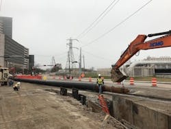
As a result of the devastating effects of Hurricane Harvey in Houston, the main sanitary sewer system of the Texas Medical Center was seriously impacted. The impact was mainly reflected in two cave-ins produced as a result of the collapse of a rectangular sanitary sewer concrete box underneath North MacGregor Way and a 30-in. pipe segment underneath Braeswood Boulevard.
In conjunction with IPR South Central, the city decided to perform the repairs and rehabilitation of the sanitary sewer system throughout the execution of a project involving two different phases. Texas Medical Center required extensive traffic control regulations due to the high volume of traffic.
The first phase included the repair of the concrete box sewer and rehabilitation of 1,357 ft of a 60-in. diameter pipe using a fiberglass liner to install more than 600 ft in two different shots. The second phase used cured-in-place pipe (CIPP) for 18-in., 30-in. and 36-in. diameter pipes at a total of 1,052 ln ft. IPR proposed a water installation with a pre-liner installed prior to the CIPP liner to avoid any resin washouts or imperfections.
A fiberglass-reinforced liner was used for 48-in. and 60-in. diameter pipes at 2,960 ln ft to increase the structural integrity of the liner. IPR also identified a 157 ft long, 48-in. diameter pipe located under a street connecting to a junction box. After a cave-in occurred on a 135 ft, 30-in. line at a sidewalk, IPR realized much of the segment was missing pipe. It identified pipe bursting as the best solution for the aforementioned portion of rehabilitation.
IPR proposed to rehabilitate the pipe with the EcoCast method to avoid a transition CIPP liner and to minimize the risk of installation, due to the location being a highly trafficked area with limited access to the downstream manhole.
Southeast Treatment Plant Sewer System Updates
|
Location San Francisco, Calif. Size 250 MGD Cost $9,536,000 Facility & Project Owner San Francisco Public Utilities Commission Designer San Francisco Public Works Contractor Monterey Mechanical Co. Manufacturers PACO Pumps, Bell and Gossett, Moyno Pumps, JWC Environmental, DeZurik, McKenna Engineering & Equipment Co., Cleaver-Brooks, Kohler, TESCO Controls, Worcester, Greenheck, Draeger, General MSA, Valmet, Rosemount, Pulsar, Kurz Instruments |
Located in Bayview Hunters Point, the Southeast Treatment Plant (SEP) is nestled in the midst of a mixed industrial, commercial and residential area; some neighbors are only a street’s width away from the treatment plant. The SEP is San Francisco’s largest wastewater facility, responsible for treating nearly 80% of the city’s flow.
Wastewater is transported to the SEP through a grid of transport/storage facilities, sewers and five major pump stations. On a dry day, SEP treats 57 million gal per day (mgd) and handles 160 wet tons of biosolids. During a rainstorm, it has the capacity to treat up to 250 mgd.
Built in the early 1950s, many parts of the SEP facilities represent 1940s technology and are operating well beyond useful life. In fact, the existing digesters were placed into operation in 1951. In response to the need to modernize the aging wastewater infrastructure, San Francisco Public Utilities Commision (SFPUC) launched a $6.9 billion Sewer System Improvement Program (SSIP).
SFPUC developed level of service goals for the projects to provide a compliant and reliable system to respond to catastrophic events; integrate green and grey infrastructure to manage storm water and minimize flooding; provide benefits to impacted communities; achieve economic and environmental sustainability; and maintain ratepayer affordability.
To meet these goals, a new biosolids handling facility will be built to replace the existing system at the SEP. This will be accomplished in the new biosolids digester facilities project, however, these new facilities will not start commissioning until 2023. The existing digesters and associated facilities will continue to handle all biosolids generated by primary and secondary treatment operations at SEP until all planning for the new facilities are completed. The SEP existing digester gas handling improvements project bridged the gap in digester service for the next six years until the new digester facilities are put into operations.
Aging infrastructure and process equipment, avoiding disruption to plant operations, and avoiding air permit violations were pivotal to this project. The project absorbed significant additional work scope with the replacement of approximately
300 ft of waste gas piping and appurtenances due to leaks surfacing on piping above ground during the commencement of the construction phase.
As the upgrades continue at SEP, creative thinking, attention to detail, sensitivity to local residents and the ability to adapt to unforeseen circumstances will be critical.
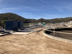
Missouri River WWTP Primary Clarifier Rehabilitation
|
Location Omaha, Neb. Size 150 mgd Cost $1,448,445 Facility & Project Owner City of Omaha Public Works Department Designer The Schemmer Associates Inc. Contractor Ace Pipe Cleaning Manufacturer Allentown AP/M Permaform Equipment Concrete placement pumps, Centripipe spincaster |
In the midst of several large projects aimed at upgrading and expanding the Missouri River Wastewater Treatment Plant, CCTV inspection of primary clarifier effluent channels revealed severe microbial induced corrosion (MIC). This caused many areas of rebar exposure, delaminated concrete and failed joints.
Structural rehabilitation of the failing concrete pipe and channel were top priority, but the most important goal was “to ensure the channels got restored back to their structural and hydraulic requirements,” according to Civil Engineer Jon Riede.
Project owners chose centrifugally-cast concrete pipe (CCCP) as the preferred rehabilitation method, as it appeared to offer the best combination of structural repair, MIC inhibition and cost-effectiveness. For permanent MIC inhibition, an MIC-resistant admixture, ConShield, was incorporated in all new concrete.
On site work took place from Jan. 16, 2018, to May 14, 2019. Although this time of year is considered dry season in Omaha, dewatering was a constant challenge and Ace crews had to monitor weather closely. At several times, teams evacuated to avoid flooding due to storm events. Access to failing pipes was limited, and staging areas were small, so a purpose-built, compact trailer for pumps and mixers was assembled for the CentriPipe process.
To compensate for cold weather, concrete material was mixed and warmed on site just prior to pumping. The channels were relined with thin, structurally sound layers, which only minimally affected pipe capacity.
The new, structurally sound pipe cast within the old channels by the CCCP process adheres to the original substrate and is usually quite thin—0.5 to 1.5 in. for this project. Original channels walls were approximately 12 in. thick. Even layer thickness was verified and assured by the use of depth pins, visual inspection, and photographic documentation.
City staff operated gates and used some bypass pumping to keep effluent channels in service during the entire project. The rehabilitation has held up with no incident and is considered to be successful.
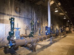
Wickenburg South WWTP Aeration Upgrade
|
Location Wickenburg, Ariz. Size 800,000 gpd Cost $1.1 million Facility & Project Owner Town of Wickenburg Designer GHD Inc. Contractor Felix Construction Co. Manufacturer Aerzen, Eaton, Flygt, Hach, ALB, Pentair, Phoenix Contact, IDEC, SSI Aeration, Utility Coatings & Fabrication |
The Wickenburg South Wastewater Treatment Plant (SWWTP) is an 800,000 gal per day wastewater treatment plant (WWTP), serving the majority of 7,400 citizens of Wickenburg, Ariz. The current SWWTP was initially introduced in 2003 with minor and single component upgrades between 2007 and 2012. The original 2003 infrastructure had remained in service and experienced major degradation and loss of full service and redundancy.
At the time, the town had begun actively managing and prioritizing how to improve and upgrade the facility to meet the town goals of sustainable compliance, available capital budget, desired schedule, resilient performance, redundancy and reduction in long-term operations, and maintenance costs.
The result of efforts by the town and GHD to evaluate projects identified the upgrade of the primary aeration basins as a top priority. The existing aeration basins consisted of two 330,000 gal basins with draft tubes and surface mechanical aerators. Besides experiencing advanced degradation, this system was found to struggle to sustain the desired dissolved oxygen (DO) concentrations and to properly monitor the DO for process control.
Other aspects of the project included upgrading to turbo blowers with fine bubble air diffusion and advanced control and to add a redundant pump for recycled activated sludge (RAS) return line to the anoxic basin.
The entire SWWTP influent had to be bypassed around the first aeration basin during the highest flows of the year. The addition of the additional RAS pump to one of the aeration basins, which was not installed at the time of the initial construction, also was a challenge. The new redundant RAS pump was to be connected to the existing large diameter return line that feeds the anoxic basin.
The significant cost savings in this projection was the reduction in long-term energy use. Removing the mechanical surface aerator, and replacing it with high-efficiency, turbo blowers and fine bubble diffused air, provided more than an 80% reduction in horsepower to operate the aeration process. Each blower is sized for the maximum daily demand for the rating of the facility.
Additionally, GHD paid special attention to providing the ability to expand the facility in the future by providing the space and connections for a future third blower. This will allow the facility to expand the primary aeration processes, in the same basins, with the same level of redundancy.
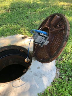
SAWS Smart City Monitoring
|
Location San Antonio, Texas Cost $300,000 Facility & Project Owner San Antonio Water System Designer SmartCover Systems Contractor SmartCover Systems, ACE Pipe Manufacturer SmartCover, Iridium Equipment Remote field units, software, advanced sonar level sensors, power supply, antenna, satellite network |
When the San Antonio Water System (SAWS) found itself struggling to keep up with the growing demands of cleaning nearly 200 sites on a monthly basis to maintain its collection system and prevent sanitary sewer overflows (SSOs), it turned
to SmartCover.
SAWS strove to transition to a real-time, condition-based, data-driven cleaning program so operators could understand and properly respond to the current actual operating conditions of its systems. This process reduces wear and tear on pipelines from routine cleaning.
To proactively approach the U.S. EPA’s national enforcement initiative to reduce storm sewer overflows, SAWS capacity, management, operations and maintenance (CMOM) program was implemented. This included about 2,400 annual monthly cleanings, as well as quarterly, semi-annual and annual cleaning to prevent SSOs. SAWS deployed 200 SmartCover units at high frequency cleaning sites to perform cleaning on an as-needed basis.
According to the EPA, 74% of SSOs are the result of blockages from cooking fats, tree roots or other debris that can result in disastrous sewer spills. Without underground visibility, sewer operators routinely clean the same pipes at great expense, whether this is needed or not. For decades, the industry has been challenged with limited options for collection system visibility and spill prevention. As a result, there is a strict high frequency cleaning culture
that exists.
Since deploying the SmartCover cleaning optimization program, there have only been 65 cleanings identified and performed at locations where 1,246 cleanings were previously scheduled. SAWS has experienced a 95% reduction in cleaning and zero
SSO incidence.
SmartCover’s technology monitors sewer pipes and transmits real time data analysis via military grade satellite communications to alert sewer operators exactly where and when to clean.
The combination of real-time monitoring and trend analysis provided powerful, predictive insights into the behavior of the collection system, enabling visibility of potential problem days or even weeks ahead. At the same time, continuous overflow protection is provided, only dispatching cleaning crews as needed.