How to Avoid Submersible Pump Problems in Motors
About the author:
Tom Sgritta is the global submersible marketing manager-industrial for Franklin Electric.
Submersible motor use in municipal systems is not new. The advantages of submersible motors are well known to this industry. Since these motors are placed deep into the earth, in a relatively stable environment, they are immune to the weather and environmental factors that plague hollow shaft motors driving conventional line shaft turbines (LSTs). These motors and pumps eliminate the drive shaft and bearing systems of LSTs, thus reducing the mechanical complexity and required maintenance. Oil does not drip into the well for bearing lubrication. Wells can be located adjacent to housing areas. Submersibles also do not require structures to enclose them and do not produce surface noise.
Submersible Pump Problems
Standard water well types of submersible motors are water (water/glycol) filled and rely on water as the internal lubrication for the motor. These motors are extremely reliable when applied within their design limits of temperature, hydraulic loading and power requirements. Typical agricultural, domestic and municipal systems are excellent applications for these motors. Unfortunately, these motors often are used in applications that unknowingly exceed the design criteria of the motors. As a result, failures occur, and the advantages of these motors are lost or quickly forgotten.
The following problems are typical in municipal applications and result in the failure of motors.
How Do You Protect a Submersible Pump?
The most common causes for submersible pump failure fall into five categories. These categories include temperature and overheating, hydraulic loading, motor seals, voltage supply and voltage spikes.
Submersible Motor Temperature & Overheating Problems
A very common problem affecting the motors is over-temperature. Causes for over-temperature include pumping hot water, overloading of the motor by the pump, loss of cooling flow past the motor, ochre or scale buildup and frequent motor starts and stops.
Submersible motors somehow must cool themselves. This is accomplished almost universally by transferring the motor's internally generated heat to the water that is flowing past the motor and into the pump. Most standard water well motors are designed to do this but add little safety margin (safety margins add cost).
The thrust bearing supports the pump's thrust weight of the water column being lifted by the pump. In standard water well motors this thrust bearing is a water lubricated "Kingsbury" type of bearing. A very small film of water between the main elements of the thrust bearing provides lubrication between the two bearing surfaces. If the motor overheats for any reason, this water film can approach its boiling point. If it boils, the lubricating film is lost. At this point, the bearing surfaces come into contact with each other and rapid heating takes place. Catastrophic failure of the thrust bearing is likely to occur.
Stator failure is another problem that occurs when motors overheat. Typical wet wound, water-filled submersibles use a PVC insulation that insulates the copper windings while immersed in water. This wire usually has a maximum usable temperature of between 70º C for standard motors to about 100º C for higher temperature motors. Once these temperatures are exceeded, the insulation system is damaged and a winding turn to turn, winding phase to phase or winding phase to ground fault becomes likely. Once these faults develop, failure of the motor is unavoidable.
Hydraulic Loading
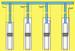
Another problematic area for submersibles in municipal applications is hydraulic shock loading or water hammer. Water hammer occurs when a rapidly moving column of water encounters an obstacle or suddenly changes velocity. The use of multiple pumps on a common supply manifold is a prime cause of water hammer. When a pump turns on or off, water hammer is generated. Additionally, when any kind of valving is actuated, water hammer can occur.
Check valves in the pump discharge string and at the well head are recommended by all manufactures to reduce water hammer. Unfortunately, check valves may be of the wrong type, may be simply not used or may become corroded over time.
When water hammer occurs, there is a sudden down thrust transmitted through the pump onto the motor's thrust bearing. This can cause several undesirable things to happen.
Most standard water well motors use some type of rotating carbon thrust bearing running on stainless steel thrust pads. Carbon is an excellent material for bearings when the lubricant is water and water hammer is not severe. Carbon, while very hard and durable, is a brittle material. When hard, brittle materials are subjected to shock loading they can shatter. Extreme water hammer is known to completely shatter thrust bearings, causing motor failure.
Standard thrust bearings in water-filled motors are lubricated by a thin water film. Water has a low viscosity. When put under a shock load, the water film in the bearing can be driven from between the bearing surfaces resulting in insufficient lubrication. This condition can lead to hot spots, excessive wear and bearing failure.
Motor Seals
The seals at the motor's shaft keep the well fluid from getting into the motor. Both water-filled and oil-filled motors need to do this in order to keep abrasives out of the internal motor bearings. Additionally, in aggressive water, the low pH of acids or high salt levels can cause internal corrosion if allowed into the motor.
Standard water well duty submersible motors use a single mechanical seal. This seal can be of carbon/ceramic or silicon/carbide. Silicon carbide is considered a premium seal and is a harder seal than carbon ceramic. It is very useful in sandy well applications.
Voltage Supply
Submersible motors, like any electric motor, require a good voltage supply at the motor terminals. A leading cause of motor failure is under-voltage or voltage spikes.
Under-voltage typically is caused by sizing the drop cables (supply cables) too small or by the utility grid supplying low voltage to the site. Ohms law is always in effect in electrical circuits (V=I ¥ Z). Voltage equals the current flowing in a circuit multiplied by the impedance (the resistance of a cable is usually the majority of the impedance).
As smaller diameter drop cables are used, the resistance increases. As the resistance of the lead goes up, the voltage drop in the lead goes up as well for a given operating current.
For a fixed supply voltage from a transformer, as the voltage drop in the lead goes up, the terminal voltage at the motor must go down. As the voltage at the motor terminals fall, the motor must have more current to produce the same horsepower (which induction motors want to do). Eventually, too much current is flowing for the size of winding wires used in the motor and internal overheating begins to take place. This leads to failure of the motor.
In large motors commonly used in the municipal industry, large power cables typically are required and used. If the setting of the motor and pump are deep, very large and very expensive cables must be used in order to provide the rated voltage at the motor's terminals.
An economical alternative to this is to design the motor to operate at higher voltages. If a motor is designed to operate at higher voltages, the required full load current will go down. As the current required goes down, the size of the drop cable can be reduced as well. Smaller drop cables use less copper and are less expensive-sometimes much less expensive.
Consider a 200 hp motor. If the motor is designed for 460 volts, the full load current is 247 amps. If, however, the motor is designed to operate at 2,300 volts, the full load current falls to 49.4 amps.
In this situation, if a 500 ft setting depth is used, the recommended drop cable goes from a size 250 MCM cable for the 460 volt motor to a #8 size cable for the 2,300 volt motor. Higher voltage cable and components with better insulating values must be used, but the cost of these typically is more than offset by the savings in the copper of the drop cable. Smaller drop cables also are much easier for the installation crew to handle.
Voltage Spikes
A very serious problem for all induction motors is voltage spikes. These spikes typically are very short in duration and high in voltage. These spikes can be generated by lightning, other motors turning off or utility switch-gear opening.
In municipal well fields with multiple pumps and motors running, this can be a serious problem. Each time one of these motors is switched off, the stored inductive energy in the magnetic circuit of the motor is dumped back onto the power lines. This creates a very short but very high voltage spike.
These spikes often are of a greater voltage level than the motor's insulation system can tolerate and will burn through the insulation. Once this occurs, the motor has a potential site for an internal short and current can flow in a path that it was not designed for. Typically, this will raise the temperature of the windings near the shorted spot and further burning will take place until a catastrophic failure occurs.
If the voltage spike is large enough and has enough energy (e.g., lightning strike), it can completely burn a hole in the case of the motor.
Motor manufactures can do little to protect against severe voltage spike problems. For this reason, external surge protection mounted near the motor starter is recommended. This tends to "clip" the voltage spike before it can travel down the cables to reach the motor. These surge protectors do nothing until the voltage reaches a certain critical value. At that point, they begin to conduct current and continue to do so until the voltage falls below the critical value. Large power distribution transformers that feed these motors also should be protected because these large voltage spikes can damage them as well. Warning: Consult with local suppliers or engineers for properly selecting and applying these devices.
These are the typical problems that occur in municipal operations using submersible motors. Failures never seem to occur at a convenient time. They are always a nuisance at best and more often a major problem.
This article was originally published on Dec. 27, 2001. It has been revised for clarity.