5 Top Motor Issues for VFDs
About the author:
Luke Lancaster is vice president of sales for Energy Management Corp. Lancaster can be reached at [email protected].
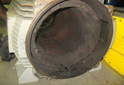
1. VFDs can wreck motor windings.
VFDs control motors with a simulated sine\ wave known as pulse width modulation (PWM). The problem is that peak voltages created by the VFD can often get high enough to break through motor insulation and short out motor windings. The first thing that can protect motors against this type of failure is to use “VFD-rated” motors. Over time this term has been broadly misused. As a quick summary, the National Electrical Manufacturer’s Association (NEMA) Motors and Generators guidelines (MG1) Part 31 is the specification for VFD-rated motors and specifies the use of premium VFD insulation. This specification is what makes a motor “VFD-rated” as defined by NEMA. Be sure to include this on a check list or spec when purchasing new motors for VFD usage.
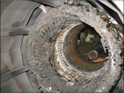
2) VFDs can destroy motor bearings.
Even if you use a “VFD-rated” motor as defined by NEMA MG1 part 31, the motor is still unprotected from shaft currents created by VFDs. These shaft currents take functional and meticulously polished motor bearings and aggressively turn them into inoperative works of industrial art. This is a result of millions of little arcs per hour discharging through the motor bearings. These arcs destructively cause pitting, frosting and fluting in motor bearings and bearing races, resulting in premature motor failure.
There is no magic bullet to send these shaft currents to the afterlife. However, one can redirect and neutralize the harmful effects on the motor and motor bearings a few different ways. This can be accomplished through a combination of technologies, such as shaft grounding rings, grounding straps, ceramic bearings, insulated motor housings and even coated bearing races. The best solution or combination of solutions will vary based on your specific application.
RELATED: Understanding the Ins & Outs of Using a Drive as a Sensor [Video]
3. VFDs burn up motors because they cannot cool themselves.
Generally, when a VFD is used on a motor, it is because it will not be run at full speed (at least not all the time). As the motor slows down, it gets less cooling because the motor’s internal cooling fan is not rotating at full speed and therefore is not providing optimal cooling. It is important to note that this is not only the case for extremely low speeds, say below 20hz, because anything under the full-rated motor speed reduces the cooling fans effectiveness and results in increased heat, lessening the motor’s operating life.
Unless the motor is continually running at extremely slow speeds, correcting this problem is fairly simple. Make sure that when a new motor is purchased it is nameplated with a service factor of 1.15 or more. Some may be thinking, “when a motor is operated from a VFD the service factor goes away,” and it may be correct. However, the increased service factor will give that extra thermal margin to allow the motor to run cool and have a normal life expectancy.
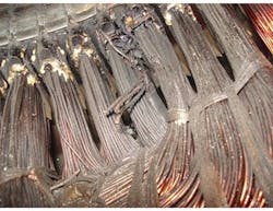
4. VFDs nuke motors with long leads.
On long motor lead applications, the VFD PWM pulses build on each other, creating peak voltages that quickly break down motor insulation and short motor windings. I recently spoke to an electrical superintendent that lost eight inverter-duty rated 500-hp motors in less than three months because of this issue. These were high quality motors and not only would any motor have failed in this situation, but some would have likely failed sooner as the peak voltages exceeded 1,500 VDC. For reference, lead lengths in this particular situation were less than 400 feet from VFD to motor.
Rules of thumb vary, take a hard look at applications that have cable runs over 100 feet (30 meters). When evaluating the cost of downtime on critical applications or the cost to push and pull submersible pump motors, it makes taking unnecessary risks seem irrational.
There are three solutions that are commonly considered when addressing this problem. The first is the simplest, which is to select a VFD that will automatically adjust its transistors’ switching and limit voltage spikes on long lead applications. This technology has been referred to as “soft PWM,” and the data suggests it will perform favorably in many applications. A NEMA MG1 part 31 motor should still be used.
Second is to install a dV/dt filter on the output of the VFD, which will typically guarantee limiting peak voltage spikes to about 975 VDC on a 480 VDC system. Generally, if a motor meets the NEMA MG1 part 30 or part 31 standards, a dV/dt filter will work really well for most situations.
The third is a premium option, which is the use of sine wave filters on the output of the VFD. A sine wave filter converts the PWM wave from a VFD into a clean sine wave and will keep voltage peaks at or below approximately 800 VDC on 480 VDC systems. Sine wave filters work extraordinarily well but are often as much or more than the cost of a VFD chassis. However, that cost may be irrelevant when compared to the expense of downtime or push and pull costs.
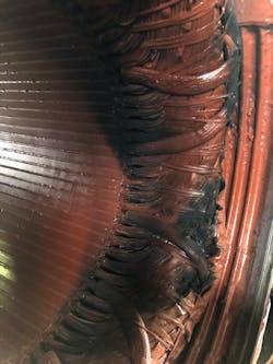
5. VFDs cause mechanical motor breakdown with centrifugal forces.
Over-speeding motors with VFDs can result in a variety of motor-related mechanical issues. Increased vibration is generally where this problem begins and it cascades into accelerated bearing wear, general balancing issues and complex system vibration issues, which can even cause failures on the driven equipment.
It is important to mention that VFDs will gladly run electric motors over their rated speed. Over-speeding motors is fairly common for several reasons but is generally used as a way to compensate for some sort of mechanical shortcoming. Standard NEMA motors are designed to run up to 25% above their rated speed, and as long as the current draw is under the motor’s full load amp rating, there should not be a problem. Just remember that when a motor is over-sped beyond its full load amp rating, it can lose available torque at the motor shaft. This can result in a stalled motor condition, which generally is not damaging to the motor but can sure be annoying.
This information will better prepare managers to have an educated discussion with staff and suppliers to make sure they are are getting the best equipment for their situation, while ensuring proper motor health.