About the author: Jason Warren, P.E., is a lead hydraulic engineer at Lockwood, Andrews & Newnam Inc. Warren can be reached at [email protected].
Whether recognized or not, control Valves are everywhere in water and wastewater systems. From small applications, such as the quarter-inch valve in a faucet, to large applications, like the 30-in. valve controlling the water level in the local reservoir, it is important to select the proper valve for each individual application.
Types of Control Valves
Numerous types of control valves exist that can be customized with hundreds of options. Each valve design provides distinct flow characteristics, which can vary even between manufacturers. Below is a basic overview of commonly installed control valves and some differentiators:
Ball. Quarter-turn valve offering full port flow. Best suited for clean water applications. Neutral cost in comparison with other control valves.
Butterfly. Quarter-turn valve offering short lay length and lower weight. Ideally used for isolation rather than system control. Only suitable for clean water applications. Most capital cost-effective option.
Cone. Quarter-turn valve offering full port flow. Best suited for clean water applications. Rugged, long-lasting design. Cost-prohibitive at larger sizes.
Globe. Diaphragm valve offering control through nearly 100% of the closing stroke. Only suitable for clean water applications. Can be cost-prohibitive at larger sizes.
Plug. Quarter-turn valve offering full port flow. Best suited for unscreened raw water or wastewater applications. Can be cost-prohibitive at larger sizes.
Sleeve. Piston-style valve offering high head loss and control through nearly 100% of the closing stroke. Only suitable for clean water. Comparably cost-prohibitive.
Factors Affecting Selection
Without proper control valve selection, numerous issues can arise. Oversizing can limit or disable the ability to control the system. Under-sizing can cause high velocities and create cavitation, causing damage to the valve and potential seating failure. Improper type selection can cause valve plugging or unnecessary capital expense. In order to select the appropriate valve for an application, a few questions must first be answered:
- What is the valve aiming to control (flow, pressure, level, etc.)?
- What media is being controlled (raw water, potable water, wastewater, etc.)?
- Are there dimensional constraints?
- What is the range of operational scenarios?
- Are there potential future scenarios to consider?
Once these questions have been evaluated, the answers can be used to determine an optimal valve selection for each application.
Case Study – Saginaw Midland Municipal Water Supply Corp.
The Saginaw Midland Municipal Water Supply Corp. (SMMWSC) provides raw water to the cities of Saginaw and Midland, Mich., as well as other small agricultural and industrial customers. Raw water is sourced from a Lake Huron intake near Whitestone Point and pumped through parallel transmission lines to the customer municipality water treatment plants. The system also includes two re-pump stations that can be utilized or bypassed as necessary. Further, flow can be diverted to the Kochville reservoir, a 180-million-gal raw water storage reservoir, instead of being fed directly to the Saginaw treatment plant. The SMMWSC was approached by Bay City to use existing excess system capacity to supply raw water to a new membrane treatment plant. This required a new connection to an existing transmission main and a proposed flow control valve.
Lockwood, Andrews & Newnam (LAN), a planning, engineering and program management firm, was contracted by the SMMWSC to design the proposed connection and flow control system. Due to the complexity of the system, numerous operational scenarios had to be evaluated, including the minimum daily demand of approximately 35 mgd to the near-term maximum daily demand of approximately 93 mgd. The proposed Bay City membrane treatment plant was being designed for expansion; thus, a future scenario also had to be evaluated with a long-term SMMWSC system maximum daily demand of 123 mgd. During these analyses, the range of flow to the Bay City plant was 5.5 to 22.2 mgd.
Selecting a Control Valve
After extensive hydraulic modeling of the system and its different scenarios, required upstream and downstream pressures for the valves were obtained. This allowed each scenario to be associated with a Bay City flow demand and a required pressure drop across the flow control valve. Using the Cv coefficient method of pressure loss calculation show in the equation below with the associated flow and pressure change, a required valve coefficient was calculated for each scenario.
The next step was to identify the style of valves that would be most applicable for the proposed scenario. The proposed system media was raw water and there were no dimensional constraints. Capital and operational costs were to be kept as low as practical but were not a limiting factor in design; therefore, the analysis focused on ball- and cone-style valves with the option of a sleeve valve if required.
The following step was to identify the size of each valve style that could meet the required head loss coefficient. Due to nuances in design, each manufacturer publishes valve characteristics including full open Cv, in addition to % Cv vs. % valve stroke (open) data. While uncommon, this means there is the potential for manufacturers of the same style valve to require different sizes to optimize a scenario.
Once the potential valves and sizes were identified, the representative valve position for each scenario was calculated using the % Cv vs. % valve stroke information. Using this criteria, the suitable valve list was narrowed to only those valves able to operate in their optimal control range during all scenarios.
Design Challenges & Valve Selection
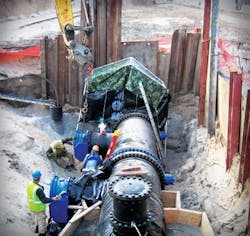
The range of scenarios for the SMMWSC application was the major design challenge for this project. Depending on demands and operations, system pressures could vary by nearly 75 lb per sq in. Further, installing a valve that did not take into account planned system expansion could have caused costly upgrades and potential system down time in the future. To account for the range of scenarios and also to provide system redundancy, dual transmission lines equipped with a flow control structure were recommended and installed. This allowed for the valves to be designed with only one in operation during lower flow scenarios, but both in operation during peak future conditions. This further enabled line velocities to be kept at recommended levels. After these evaluations were completed, the valve selected for the SMMWSC application was an 18-in. DeZurik cone valve. These valves were installed and have been in operation since the fall of 2014.
Thanks to LAN’s methodical design approach, the SMMWSC is capable of supplying the new Bay City treatment plant during all of its various operating scenarios. Further, the SMMWSC can meet its customer’s future demands without the need for costly upgrades or supply shutdowns.