Adam Kohout, P.E., is an engineer at Lockwood, Andrews & Newnam, Inc. (LAN), a national planning, engineering and program management firm. He can be reached at [email protected].
undefinedPopulation increase and jurisdiction expansion drove the City of Conroe, Texas, to build a new Conroe Central Wastewater Treatment Plant (CCWWTP) to increase system treatment capacity. The owner contracted Lockwood, Andrews & Newnam, Inc. (LAN), a national planning, engineering and program management firm, to perform the design of the CCWWTP. LAN took the opportunity to provide added value by incorporating an advanced treatment into the design of the facility. This advanced treatment design, a two-stage process known as the A/B Process, would allow for beneficial anaerobic digestion of the two separate sludges produced. Design of the sludge processing system included blending of the two sludges, thickening, anaerobic digestion, dewatering, biogas capture, cleaning, storage, and use in power generation
To reduce capital expenditure, the A-Stage of the A/B Process was deferred to a later date. Consequently, the digestion design was altered to be aerobic, and all biogas equipment was deferred. The need for sludge blending was also deferred. These alterations to the sludge processing design allowed for a reduction in the capital cost of the initial construction. To maintain the possibility of utilizing the benefits of the A/B Process and anaerobic digestion in the future, the design alterations were made in such a way that treatment elements could easily be transitioned back to the original design. This provided the owner the option to expand the CCWWTP in the future, without abandoning structures installed in the initial construction.
Benefits of A/B Process and Anaerobic Digestion
The A-stage of the A/B Process is an activated sludge stage where small, high-rate aeration and settling basin phases physically remove a high percentage of the carbon and other organics from the wastewater stream. The B-stage is a traditional activated sludge secondary treatment stage with aeration and clarification. Since a large portion of the carbon is removed with the A-stage, the B-stage aeration can be decreased in size to focus on nitrification and nutrient removal. This results in capital savings and energy savings compared to a conventional activated sludge (CAS).
Anaerobic digestion offers key benefits over aerobic digestion. First, the lack of aeration produces energy-usage savings over aerobic digestion. Second, the biogas produced by anaerobic digestion can be captured, cleaned and utilized for power generation. This power generation is achieved with biogas-compatible generators and has the potential to offset energy usage, further increasing energy-usage savings. The carbon-rich and organic-rich sludge from the A-stage of the A/B Process is well suited for anaerobic digestion and biogas generation, making anaerobic digestion an easy decision to pair with the A/B Process.
Design Transition
The A-Stage of the process was deferred to reduce capital expenditure of the initial construction of the CCWWTP. There are planned expansions to treatment plant, and room was left in the hydraulic profile to add carbon diversion back into the treatment process at a later point, with the understanding that technologies for carbon diversion are rapidly developing. At the time when it is incorporated at the CCWWTP, a smaller or less expensive carbon diversion option than the originally designed A-Stage may be available.
The original design of the sludge processing system for the CCWWTP included multiple stages, structures, and buildings. Clarifier underflow pumps would pump waste activated sludge from each stage of the process to a blend tank, where they would be blended together, pumped through a grinder, and on to disc thickeners housed in a thickening building. After thickening, the sludge would be pumped by thickened sludge pumps, also housed in the thickening building, to two anaerobic digesters with draft tube mixers. Connections for a boiler were included as a measure to ensure appropriate temperatures would be maintained in the digester. Biogas would be taken off the anaerobic digesters, cleaned, and stored in a large inflatable storage bladder. The biogas would be used in bio-gas compatible generators or burned off with a flare. Digested sludge pumps, housed in a dewatering building, would pump the sludge to centrifuges housed in the same building. The dewatered sludge would be stored in roll-off containers for off-site disposal.
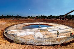
The deferral of the A-Stage necessitated alterations to the sludge processing system. Without the carbon-rich and organic-rich A-Stage sludge, it became clear that aerobic digestion would be a better option in the interim time between initial construction and the construction of future carbon diversion. Additionally, the initial construction of a blend tank was not needed. As such, alterations were made to these structures to decrease initial capital expenditure and defer items that were no longer needed. A thickener mechanism was added to the blend tank without altering its dimensions. This allowed for the deferral of the sludge thickening building and associated equipment (disc thickeners and associated pumping and piping). Because the dimensions of the tank were not altered, the ability to remove the thickening mechanism in the future and return it to service as a blend tank remained, in line with the original design.
The dimensions of the two digesters were also unchanged, however diffusers were added to the floor and blowers were added to a pad adjacent to the digesters to convert them to aerobic digesters. The draft tube mixers and roofs of the digesters were deferred upon the conversion to aerobic digestion. The need for a boiler connection was also deferred. The digesters, like the blend tank, were left the same size to accommodate the possibility of transition back to the original anaerobic design later. In such a scenario, the only requirements would be removing the diffusers and installing the draft tube mixers and roofs.
The transition of digestion from anaerobic to aerobic also allowed for the deferral of the biogas equipment. This included the biogas safety, cleaning and storage equipment, as well as the biogas-compatible generators and burn-off flare. Generators were still included in the initial construction of the CCWWTP, however they did not need to be biogas compatible. The deferral of biogas equipment was a significant initial capital cost reduction, and the necessary footprint for the equipment was maintained to provide space for its addition in the future.
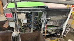
As an additional design alteration, the digested sludge pumps were moved out of the dewatering building, underneath a canopy adjacent to the dewatering building. This allowed for the building footprint to be reduced, providing further cost savings.
Take-Aways
While the A/B Process and anaerobic digestion originally designed for the CCWWTP would have provided measurable benefits, the most pressing need for the owner/operator was to alleviate financial burden with the original construction. The deferral of some aspects of the CCWWTP provided that financial alleviation, while the design flexibility allowed the owner the option of reaping the A/B process benefits in the future. LAN also provided documentation and guidance to the owner/operator on how to best approach transitioning back to the original design when the opportunity arises in the future. The construction of the CCWWTP, a $60 million project, is currently underway and scheduled to be completed in early 2022.


