Backgrinding Wastewater Filtration
About the author: Simon Yang is Asia applications engineering manager for Porex Corp. Yang can be reached at [email protected].
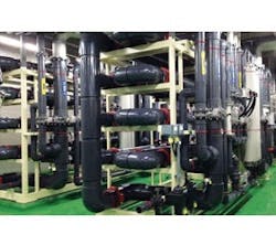
One of the largest semiconductor manufacturing companies in Korea recently received a 3,000-cu-meter-per-day tubular membrane filter (TMF) system for wafer backgrinding water reclamation.
During the deposition, etching and intermediate chemical mechanical polishing stages, the thickness of a semiconductor integrated circuit (IC) wafer is typically kept at three or more times greater than required for the final device. The extra thickness ensures handling strength and geometric stability during those manufacturing processes. Prior to IC packaging, the wafer is ground to final thickness in a backgrinding process. Large amounts of ultrapure water are used for rinsing off the fine silicon particles and cooling the wafer during the grinding operation; this is discharged from the wafer packaging facility. This wastewater primarily contains high-value ultrapure water, silicon and colloidal silica particles.
In some cases, a small amount of grinding additive fluid may be present. If the fine particles can be removed, the treated water is exceptionally pure due to the resulting low total dissolved solids (TDS) (low conductivity) and can be recycled. The packaging facility’s ultrapure watermaking costs are reduced by introducing this recycled water to intermediate or tertiary purification stages. Wastewater discharge costs also are reduced.
Challenges With Conventional Treatment
Filtration with hollow-fiber ultrafiltration (UF) presents the following challenges:
- Large amounts of small, sharp silicon particles result in high turbidity loading.
- Sharp particles can cut and damage the hollow fiber, resulting in unpredictable and poor filtrate.
- Low recovery rates occur due to frequent backwash with permeate water.
- Membrane flux is difficult to completely recover with chemical cleaning due to poor chemical resistance of the hollow-fiber UF elements. Membrane fouling substances (silicon/silica/organics) cannot be removed with high-concentration chemical cleaning solutions.
- Coagulation and sedimentation with a clarifier present the following challenges:
- Tiny particles tend to remain suspended in water and do not settle, even with large amounts of coagulants added.
- At times, hydrogen gas bubbles are released due to caustic soda dosage together with coagulant, which is necessary for precipitation. This makes efficient sedimentation harder to achieve.
- Chemical dosing changes the water characteristics, especially the TDS level, which can increase significantly. This high-TDS water may not be economical to recycle.
- The process is lengthy if water reclamation is desired.
- The filtrate quality is not as high compared with membrane filtration.
- Clarifier system performance may be unstable.
TMF Modules
Using Porex 0.05-µ TMF modules, Veolia built a system for the solid/liquid separation process without the need for any chemical dosing. This filtered water then is sent to a reverse osmosis (RO) system for ionic silica removal only—not for desalination—because the original influent water conductivity is less than 10 µs/cm. The RO product water then is sent back to the workshop for reuse as deionized (DI) water. The slurry from the TMF system is sent to the facility’s central wastewater system for further treatment.
The influent suspended solids concentration is 500 to 1,000 mg/L. A disc centrifuge analysis shows that most of the particles are larger than 50 nm (0.05 µ). The mixed raw wastewater has a brown appearance with numerous fine particles in the liquid.
The system capacity is designed at 3,000 cu meters per day. Currently the plant utilizes 2,000 cu meters per day, and as its processing volume grows, it will utilize the entire 3,000-cu-meter-per-day capacity.
TMF Characteristics & Advantages
When used to treat backgrinding wastewater, this system provides the following benefits:
- Combined with a filter press, this system will divide the wastewater into two parts: filtrate water and dewatered sludge cake. There is no concentrated or reject water sent to drain. This results in a nearly 100% recovery rate (if the squeezed water returns to the main reclaim system).
- No chemicals are dosed into the wastewater, so sludge can be reused with appropriate processing.
- There is no pretreatment stage. The entire system operates based on simple, physical solid/liquid separation.
- It produces high filtrate water quality. Particles larger than the membrane pore size will be rejected. The treated water quality is equal to UF product water.
- The TMF membrane tube has high abrasion resistance. The membrane is not destroyed by sharp silicon particles; normally that is the most significant problem when attempting to use hollow-fiber UF membranes for this type of wastewater. Hollow-fiber breakage or plugging happens due to random particle shape, high solids concentration, small lumen diameter and lack of a membrane-supporting substrate layer.
- Maintenance is easy. The system can be designed for automatic operation, and can be turned to service mode from standby mode at any time.
- The Porex TMF has high resistance to fouling compared with hollow-fiber membranes. The membrane flux can be restored because strong chemical solutions can be used during clean in place.
- The system has a smaller footprint than some conventional methods.
- The system has the ability to expand. Water capacity can be enlarged by simply adding more TMF skids or modules.
Additional System Information
The module configuration of 61-tube TMF modules were applied in the wafer backgrinding application system. Specifications of the modules include:
- Sixty-one half-in. membrane tubes in each module;
- Membrane pore size of 0.05 µ;
- 4.25 sq meters of effective membrane filtration area per module;
- PE substrate tube with PVDF membrane; and
- PVC module housing.
The backgrinding wastewater in this system is collected in the equalization tank, then pumped to the TMF concentration tank (also called the circulation tank). The water then is fed into the TMF unit for solid/liquid separation. Most of the water stream will recycle between the TMF modules and concentration tank in a cross-flow filtration process. Filtered water is sent to a separate product water tank and fed into an RO system for ionic-type silica removal. It then is reused as DI water. Silicon particles that are rejected by the TMF membranes accumulate in the concentration tank during operation. Typically, the partially concentrated liquid is continuously bled off at a set rate. Currently, this stream, and approximately 95 cu meters per day of RO reject water, are sent to the existing wastewater station for further treatment. No chemicals are fed into the system during normal service.
Operation Status
Construction was completed and system commissioning began in July 2013. The system performance has met or exceeded the original design specifications.
As a unique total solution for backgrinding wastewater reclamation, TMF was selected and installed as a key component in this system. The membranes’ structure and properties make it possible to achieve outstanding filtrate quality together with 95% recovery rates in a simplified treatment process.
This system not only reduces wastewater discharge volume, but also recovers a large amount of high-quality DI water. By saving in these two areas, the end user estimates that this plant will ultimately save approximately $1 million per year in reduction of ultrapure water usage and sewer discharge fees.
The Porex TMF membranes were supplied by SI Membranes of Seoul, Korea, and the system was constructed by JM Tech Co. Ltd., also based in Korea.
Download: Here