Preventing & Controlling Transients: Part 1
Tom Walski is a Bentley Fellow for Bentley Systems. Jesse Dringoli is senior manager, technical support for Bentley Systems. Walski can be reached at [email protected]. Dringoli can be reached at [email protected].
undefinedAny time water accelerates or decelerates in a pipe, a pressure wave is created. Usually, these changes are small and can be ignored. However, larger pressure waves, referred to as transients, water hammer or surges, can cause serious problems. High pressure waves can burst pipes or open joints, while low pressures can collapse pipes or suck contaminated water into pipes. These pressure waves move quickly through water systems and die off quickly, therefore causing an impact that can go unnoticed until they cause major problems.
Prevention or control of transients is not easy or intuitive. There are many ways to reduce rapid changes in velocity or reduce the impact of water hammer, and understanding them in any detail requires a transient analysis computer model.
Almost every water utility of any size in the developed world has a hydraulic model of their distribution system. However, models used for typical design and operation of water systems usually ignore rapid changes in velocity. Understanding transients requires solving equations that can account for these rapid changes in velocity and subsequent pressure waves. For anything beyond a trivial situation, these equations cannot be solved manually, but instead require transient analysis software such as Bentley’s Hammer program.
How much work is required to advance from hydraulic models to transient models? In most cases, the data—pipe length, pipe diameter, and pipe connectivity throughout the network—required to build and run a transient model is available in the hydraulic model. For example, the WaterGEMS program contains most of the data required to construct and run the Hammer model and can be opened directly in the application. It is simply a matter of opening the model data and adding the data needed to describe transient events.
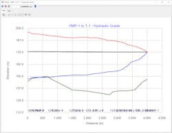
The underlying hydraulic model needs to be well-calibrated and some simplifications for typical modeling cannot be used. For example, analyzing the hydraulic grade of a portion of the system by assuming a hydraulic grade upstream of that portion being analyzed will lead to misleading transient results if the upstream system plays a significant role in the transient.
In situations where low pressure transients are being studied, the difference between the elevation of the pipe and the elevation of the ground (often used as pipe elevation) can become significant as this could influence the occurrence of vapor pockets in the pipe. On the other hand, models used for transient analysis can be skeletonized significantly since many small pipes have little influence on transients.
The following sections describe the types of data required to convert a hydraulic model (WaterGEMS or WaterCAD) into a transient model (Hammer). Once a hydraulic model has been opened in Hammer, there are several types of information that needs to be added, including:
• Wave speed;
• Description of the event that triggers the transient or water hammer;
• Description of any transient control measures; and
• Hammer calculation options.
This transient information also can be added in WaterGEMS and WaterCAD model files in preparation for a run through the Hammer application for modeling.
Water Hammer & Wave Speed
Transient wave speed depends on the properties of the pipe and the liquid. The more rigid the pipe, the faster the wave speed. The pipe properties that impact wave speed are Young’s modulus, Poisson’s ratio, wall thickness and the support for the pipe. Water properties that affect wave speed include bulk modulus of elasticity, specific gravity and the amount of entrained gases in the liquid. This application includes a wave speed calculator and a library of values for pipe and liquid properties.
While wave speed is similar for most transient model runs, the event that triggers the transient can vary widely. Causes of some types of transient events include pump trips, pump startup and shut down, rapid valve closure and opening, filling pipeline, and direct specification of flow or pressure used as boundary conditions.
Pump trips
Sudden shutdown of a pump, usually due to a power outage, is the most common, troublesome event in water distribution systems. Initially, there will be a pressure downsurge on the discharge side of the pump and a pressure upsurge on the upstream side. The momentum of the fluid changes rapidly and the ensuing pressure wave can be dramatic. The rate at which the momentum changes depends on the specific speed of the pump and its rotational speed at the time of the pump trip.
Pump startup and shutdown
Any pump startup and shutdown will change the velocity and momentum of the water. This will create transients, although for most large pumps, controls are in place to reduce the impact of the event. These can consist of pump control valves, soft starts or variable speed drives.
When control devices are involved, the time for the valve to close or the time for the motor to ramp up or down determine the impact. For gradual changes in motor output, the modeler can ramp up torque or speed. If there are no control devices, then pump inertia controls the transient as with pump trips. If a vapor pocket has formed after a pump shutdown, modeling a subsequent startup of the pump may be necessary to see the impact of the collapse of vapor pockets.
Rapid valve closure and opening
Any time flow rates change, a transient pressure wave is created. The most serious of these changes are caused by rapid opening or closing of a valve or hydrant. The critical input is the time over which the valve changes position accompanied by a valve characteristic curve, which describes how the hydraulic properties of the valve change with position. The relationship between flow through the valve and valve position is not linear. The first few turns to open the valve or the last few in closing the valve usually have the greatest effect on flow.
Filling pipeline
As a pipe is filled, air is expelled through an air release valve or an open orifice. Resistance from the opening to the atmosphere can cause a damaging transient when the air is fully expelled. The model initial conditions need to describe the initial air pocket (void space) size.
Directly specifying flow or pressure as boundary conditions
Users also can directly specify some known pattern of flow or head as boundary conditions to create transient events. This can correspond to a large water user starting or stopping flow, and can be specified as a single pattern or a repeating pattern.
Control Measures for Transients
Transients eventually are dampened out by friction, storage tanks and open orifices in the system. Most of the information needed to determine damping and other phenomena which depend on system geometry are available in the WaterGEMS or WaterCAD hydraulic model. However, there are several types of devices that can prevent, control and hasten the decay of transient pressure. In the hydraulic model, it is better to place the control devices on a Tee from the main pipeline in the model so they can easily be turned on and off from one scenario to another.
Open surge tanks
Surge tanks with a free surface dampen pressure waves by enabling water to flow from the pipe into the tank during a positive wave and from the tank into the pipe during a negative wave. This control primarily depends on the hydraulic grade in the tank and the size of the pipe leading to the tank. If the surge tank cannot be built tall enough to match the system hydraulic grade, a check valve may be installed to prevent inflow, creating what is called a one-way surge tank.
In addition to specifying the type of surge tank, the user also must describe the diameter of the tank orifice and head loss coefficient, the weir length and coefficient for the overflow, and whether it has a check valve.
Pressurized surge tanks
Pressurized surge tanks, which often are called hydropneumatic tanks or gas vessels, have a gas pocket above the water surface in the tank. Pressurized surge tanks have a great deal of flexibility and require significantly more data to adequately describe them to the model. The user must provide the volume—whether the tank is sealed or vented—the diameter of the pipe connecting the tank and the water main, and whether it has a flexible bladder.
Air valves
Air valves are used to bleed air out of the pipe and/or introduce air into the pipe to prevent negative pressure. The time to close and orifice sizes are the most important inputs controlling valve behavior. Hammer can help size the orifices controlling air inflow and outflow rates needed to control water hammer. The user must specify the type of air valve and the dimeter of the inflow and outflow orifices (whether the inflow/outflow is calculated based on an orifice diameter or an air-flow curve).
Pump controls
The usual way to describe how pump controls influence transients is to specify the time it takes to transition from full flow to zero or zero to full speed. The user must specify the type of startup/shutdown, the pump’s inertia and speed, and whether it has a control valve or simple check valve.
Surge relief valves/rupture disks
Surge relief valves discharge high pressure water to reduce potentially damaging pressure. The key inputs here are the pressure setting/spring constant at which the valve opens and the orifice size. For surge relief valves and rupture disks, the user must specify the threshold pressure at which it opens and for the valve, the diameter and spring constant.
Surge anticipator valve
A surge anticipator valve can open quickly on a pump trip and allow a reflected high-pressure transient to vent without causing damage. This is modeled by specifying the type of valve mechanism (needle, butterfly or globe), the size of the orifice and discharge coefficient when fully open.
Editor’s Note: Water Hammer for Everyone Part 2 will appear in the October issue of WWD.