Lift & Pump
Steve von Gontard is sales representative for MWI Pump Rental Tampa. Von Gontard can be reached at [email protected].
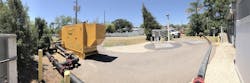
undefinedThe typical lift station bypass requires a primary and a backup sound-attenuated centrifugal or hydraulic pump. These units pump from the influent manhole prior to the wet well and discharge into an external pump-out. Typically, these pumps are set up on auto start/stop floats or transducers to minimize run time and the amount of sound pollution. Most municipalities require a telemetry system for monitoring the performance of the system. The following is a list of steps and information to complete a successful lift station rehabilitation.
Steps for Pre-Mobilization
- Review the project plans for the scope of work. Ask, “Is it a complete rehab including mechanical piping, electrical, new pumps and lining of the wet well and/or the valve vault?”
- Review the specifications for bypass requirements and ask these questions: What type of pumps are required? Is sound attenuation required for quiet zones? Is an electric primary and diesel backup preferred? What redundancy is required? Are telemetry systems required?
- Determine max flow and max head pressure for the station. This information may be available in the plans and specs, or you may have to get this information from county records, plant operators, engineers or elsewhere.
- As a precautionary suggestion, add a 20% safety factor to all performance conditions for surges, rain events and rental pump wear.
- Run total dynamic head calculations to determine the pump size needed and the hoses and fittings that can handle the system pressure.
Perform a Site Visit
- Determine the suction point. Ask, “Can the equipment pump out of the influent manhole? Are there multiple pipes going into the lift station that will require multiple systems? Can I install a pipe plug in the downstream pipe of the manhole and surcharge the manhole, or do I need to use a flow through pipe plug in the manhole or wet well?”
- Determine the discharge point and ask the following: “Am I discharging into the pump-out in valve vault, wet well or a separate manhole? What size and type is the connection point? Is it a flange or a quick-connect fitting?”
- Take into consideration the scope of work of the rehabilitation and any obstacles that will interfere with the bypass system.
- Decide where to place the pumps. First, measure the suction hose length to the manhole and the depth of the manhole, then measure the discharge hose length to the discharge point. Include any applicable 90-degree elbows, check valves, tees/wyes/manifolds, or other necessities. Check valves are essential on bypass systems and should be placed inline prior to connecting the primary and backup pumps to the main trunk discharge line.
Mobilization/Setup/Startup
- If using a rigid pipe, install the bypass system from the discharge point working backwards to the pumps. Suction hoses will provide flexibility to get into the influent manhole.
- Measure the depth of the influent manhole and height of the strainer to set low/stop floats above the top of strainer. Set the high/start float at the desired level to achieve a run-time of approximately 10 minutes, to allow for battery recharge. Please note, the backup system high/start float should be slightly higher than the primary high/start float. Determine the spill point on the system and stay below this level.
- Secure floats in a manner that allows them to freely move up and down without getting tangled or having issues from turbulence. A PVC float tree is recommended. Simply attach the floats to this tree to keep them functioning properly.
- Test the floats and telemetry system to insure proper functionality.
- Prior to starting the bypass system, open all applicable valves on the discharge side of the bypass system and pump-out.
- Install a pipe plug, if needed. This should be performed by a trained professional with confined space certifications.
- Start up the pumps.
- Check for any air or water leaks in hoses, fittings, connections, etc.
- Monitor the bypass system cycle during peak and non-peak times to determine engine RPMs to give optimal vacuum and run-time. Run-time can be influenced by engine RPMs or the distance between the start and stop floats. Keep in mind that peak flow times change based on the environment
- Upon completion of the project, close any valves between the bypass system and pump-out. Afterwards, flush and sanitize the bypass system prior to breaking down. Keep in mind when opening fittings and connections that the bypass system is under pressure.