Tips for Effective Flow Control
Nate Ventress is a water specialist and Craig Correia is head of process automation for Festo Corp. Ventress can be reached at [email protected] or 408.859.9115. Correia can be reached at [email protected] or 508.380.4673.
undefinedSmooth opening and closing of butterfly valves has a large impact on system performance and long-term reliable operation. It not only extends the life of the valve and actuator, but protects other components and piping in the system. With systems utilizing pneumatic actuation, flow control is achieved by metering the flow of compressed air as it enters or exhausts from the actuator.
There are several problems that could occur if butterfly valves are actuated too quickly, the most notable of which is known as water hammer or hydraulic shock. This is caused by a valve closing rapidly, resulting in a buildup of pressure that quickly travels upstream. The resulting noise or vibration can damage piping or instrumentation upstream of the valve.
Properly controlled opening and closing speed of the valves protects seal material, which increases the life of the butterfly valve. The same can be said for the components inside the actuator itself.
This article identifies ways to control the speed of pneumatic actuators, both single and double acting, using effective flow control. The methods described apply to quarter-turn and linear actuators, as well as vane, rack and pinion, and scotch yoke actuators.
Flow Control Applications
Flow control is achieved through a throttling device or an orifice that limits the flow of air. The controlled flow of air in or out of a pneumatic actuator regulates the volume or rate of pressure increase against the piston or vane. This in turn regulates the rotation speed of quarter turn actuators, or the extend and retract speed of linear actuators.
Flow control valves differ from needle valves or orifices because this type of valve restricts flow in one direction but allows free flow in the opposite direction. A needle valve or orifice restricts the flow in both directions.
There are a few different ways to achieve proper flow control and therefore extend butterfly valve life.
Care should be taken to select a flow control valve that matches the environmental specifications of the application
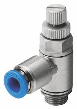
Festo, for example, offers calibrated flow control valves. The best control and performance will result from mounting an inline adjustable flow control valve directly on the pneumatic actuator. Maintenance and troubleshooting manuals can be referenced for an exact number of turns for optimal performance. This fact makes the process of adjustment simple.
Consider the pilot valve manifold
Most commonly, water treatment OEMs install the flow control valve on the pilot valve manifold. One advantage of this design is that the flow control valve comes preinstalled on the valve manifold. With this design, the flow control valve is immune to inadvertent adjustment at the plant. The system also is environmentally protected because the valve manifolds are installed in a controlled environment. Initial adjustment of these flow control valves, however, can be a challenge because the process valve might not be visible from the valve terminal. The longer the distance between the two, the harder it is to obtain precise control and system performance.
Another design that is sometimes seen is the lower-cost application of a needle valve; however, this option should be dismissed because needle valves have a major disadvantage in this application. Unlike an adjustable flow control, needle valves restrict flow of air in both directions. This fact does not allow for separate control of open and close speeds.
Consider fixed orifice control
Fixed orifice control is the least expensive control option and is available in multiple diameters. Manufacturers of treatment skids who are certain of consistency between installations can use this method effectively. Small changes in line pressure or compressed air volume, however, can have an impact on flow through an orifice. For these cases, adjustable flow control valves are preferred.
Best practices
“When in doubt meter out.” Throttling the exhaust air from the actuator, not the air entering the actuator is recommended. This design will result in a smoother motion of the actuator and valve because there is more control of the pressure differential across the vane or piston. This minimizes any stop-and-stick behavior.
Employing a flow control valve directly at the actuator also results in smoother motion because controlling air flow over a distance can create a jumping actuation due to the compressibility of air. Therefore, minimizing the volume of compressed air in the tube and mounting the flow control valve close to the actuator is preferred.
It is possible to use fixed orifice flow controls. These come is various orifice diameters and are low cost. If system pressure changes, however, the flow of air also will change. Adjustable flow controls such as the Festo GRLA offer calibrated adjustability. These valves can be tuned independently at each process valve for more precise control.
Although not ideal for smooth motion, installing inline flow control valves adjacent to the pilot valve manifold offers some advantages. The flow control valves are located in the control cabinet and can be centrally adjusted. Because the flow control valves in this design are locked in the control cabinet, only authorized personnel will have access to them. This will limit inadvertent erroneous adjustments by unauthorized personnel.
There is a proper way to adjust the speed of a process valve with flow controls: Screw the adjustment needle valve all the way into the closed position. After actuating the solenoid pilot valve, start backing out the flow control needle until the desired open/close speed of the valve is reached. Cycle the actuator multiple times and confirm the adjusted speed is satisfactory.
Download: Here
