The cities of Chaska and Shakopee are located in the southwest corner of the Twin Cities metropolitan area, 23 miles from Minneapolis, on the Minnesota River. While the cities own and operate local sanitary sewer collection systems, collected wastewater is conveyed through regional Metropolitan Council owned and operated interceptors to the Metropolitan Council’s Blue Lake Treatment Plant, where it is treated and discharged. Sewer rates are set by the city council and reflect the costs of operating and maintaining the local collection system, as well as the charges imposed by the Metropolitan Council for interceptor trunk lines and treatment.
Although it was installed in the late 1990s, the Chaska interceptor—which runs parallel to Highway 169, also known as the Shakopee Bypass—was in need of rehabilitation. The gravity sewer is composed of lined and unlined concrete pipe as well as profile wall PVC pipe in shallow reaches. The focus of this project was 7,500 linear ft of unlined reinforced concrete pipe (RCP). Inspection of the existing 72-in. RCP revealed 1.5 in.—and in some spots, up to 3 in.—of lost concrete within the headspace of the pipe. In addition, there were a few spots where RCP joint gaskets and rebar were visible.
Trenchless Option
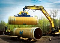
The owner, Metropolitan Council Environmental Services (MCES), along with its consultant, Brown and Caldwell, St. Paul, Minn., designed the Chaska Interceptor Improvements Phase 2 project. Together they decided to slipline the interceptor with fiberglass pipe due to its corrosion resistance. The project was awarded to Spiniello of Livingston, N.J., for its bid of $7.6 million. Spiniello rehabilitated the line by sliplining centrifugally cast, fiberglass reinforced, polymer mortar (CCFRPM) pipe to restore the structural integrity of the sewers, which were buried at depths ranging from 13 to 24 ft.
“Sliplining was chosen to minimize disturbance,” said Peter Glashagel, P.E., senior engineer, Brown and Caldwell. “Most of the run is adjacent to a major highway drainage pond with high groundwater potential, [and] this portion also having required significant rock blasting as part of the original pipeline’s installation gave plenty of reasons not to want to excavate any more than necessary.”
According to Glashagel, preparation of the line required extra cleaning work due to significant sediment and encrustation deposits at several of the existing RCP joints. It was important to clean the line of obstructions to ensure that the test mandrel and installed pipe would have proper clearance.
Hobas Pipe USA supplied 7,500 ft of 66-in., 71-psi CCFRPM pipe. “Capacity preservation often is critical on rehabilitation projects, and thin-walled CCFRPM pipe very often provides increased flow capacity because of its superior hydraulics compared to the existing sewer. Even a downsize in diameter can easily be offset by the flow factors,” said Kimberly Paggioli, P.E., vice president, marketing and quality control, Hobas Pipe USA.
Trouble-Free Installation
Spiniello excavated around Manholes 6 and 7 to create two pits about 50 ft apart for installation, and the 7,500 ft of 66-in. pipe was installed in two pushes. The longest drive was 4,200 ft and the second push was 3,300 ft.
“All pipe was installed under normal flow conditions, which was about 50% full,” said Kent Meier, superintendent, Spiniello Cos. The pushing mechanism used was an Akkerman pushing machine.
Manholes also were rehabilitated on this project. The existing manholes exhibited a deteriorating spray-on lining and 1 in. of corrosion. “Four manholes were replaced as part of the sliplining process and 10 manholes were rehabilitated by removing the RCP cone and installing a fiberglass-reinforced plastic FRP insert,” Glashagel said. “These required a special eccentric saddle cut to fit over the Hobas pipe at the bottom where the slipline pipe passed straight through the manholes. Then they cut the hole on the top of the pipe and field laminated the two fiberglass entities together.”
“Fabrication of connections between fiberglass components is routine and can be easily accomplished in the field,” said Randy Whiddon, field service manager, Hobas Pipe USA.
In Conclusion
Visual inspection of the installed line was performed by a closed-circuit television (CCTV). With no issues discovered by the CCTV, the entire annular space between the outside of the liner pipe and the inside of the existing pipe was grouted in one lift by filling the entire pipe length with sewer water to ensure it would not float.
Download: Here


